Based on when your HLM was manufactured, you may have one of two types of landing gear. For Drones shipped prior to August 2025 please begin assembly at Step 1A.
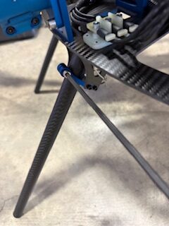
Using the included 3/16″ ball drive, secure the landing gear leg to the landing gear assembly using one of the included 1/4″-20 bolts
Using the included 3/16″ ball driver, secure the arm to the frame using two included 1/4″-20 bolts
Click or Tap to expand images
Step 1a
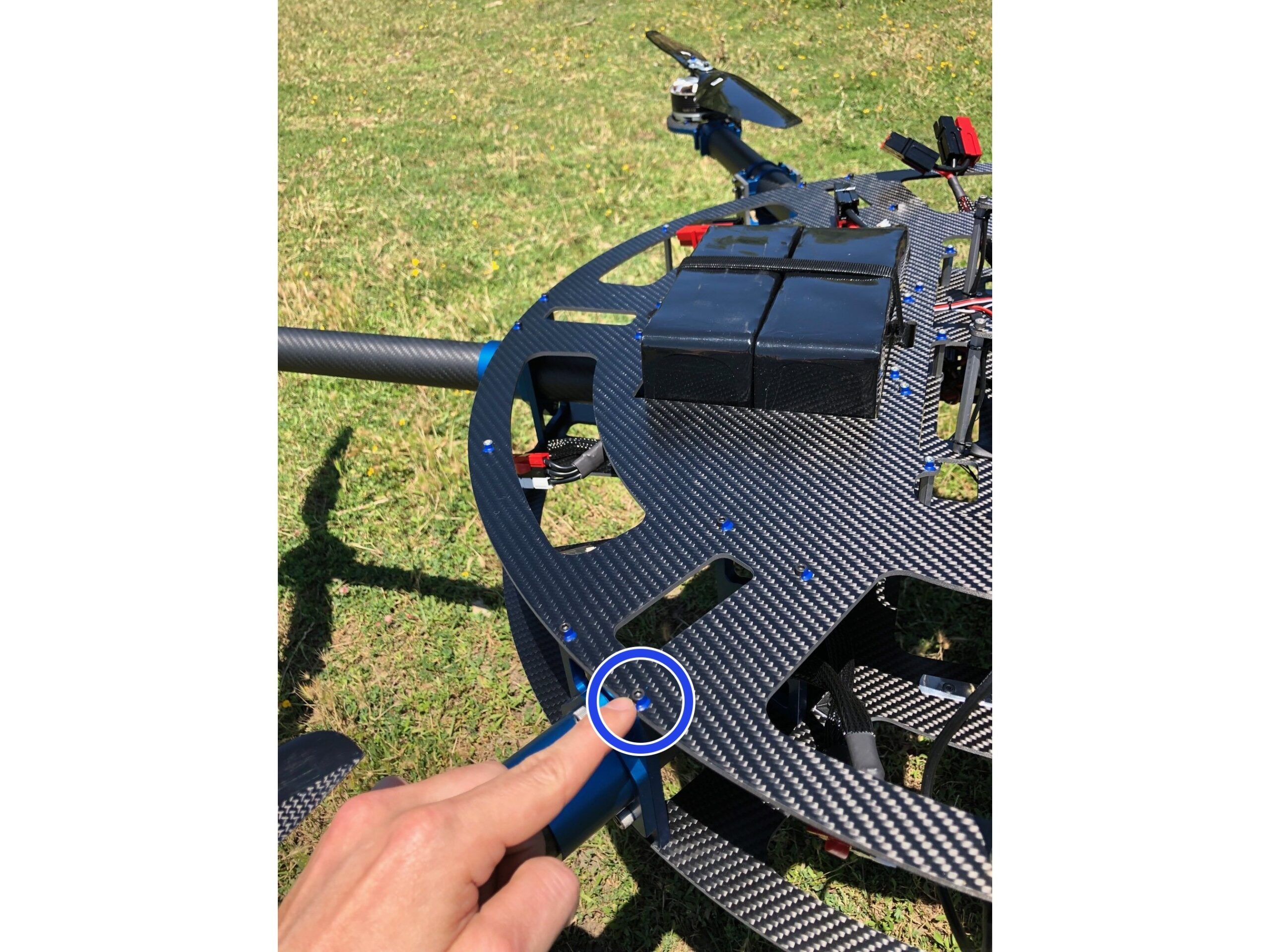
Mounting the Arms and Landing Gear Assembly (Legacy)
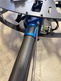
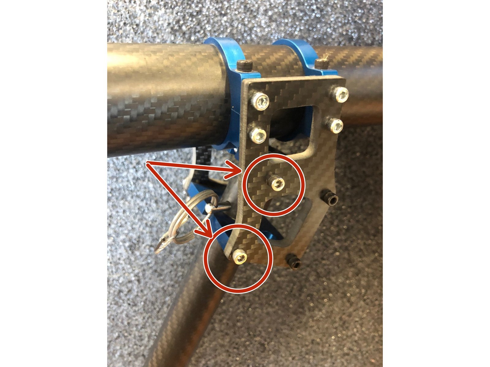
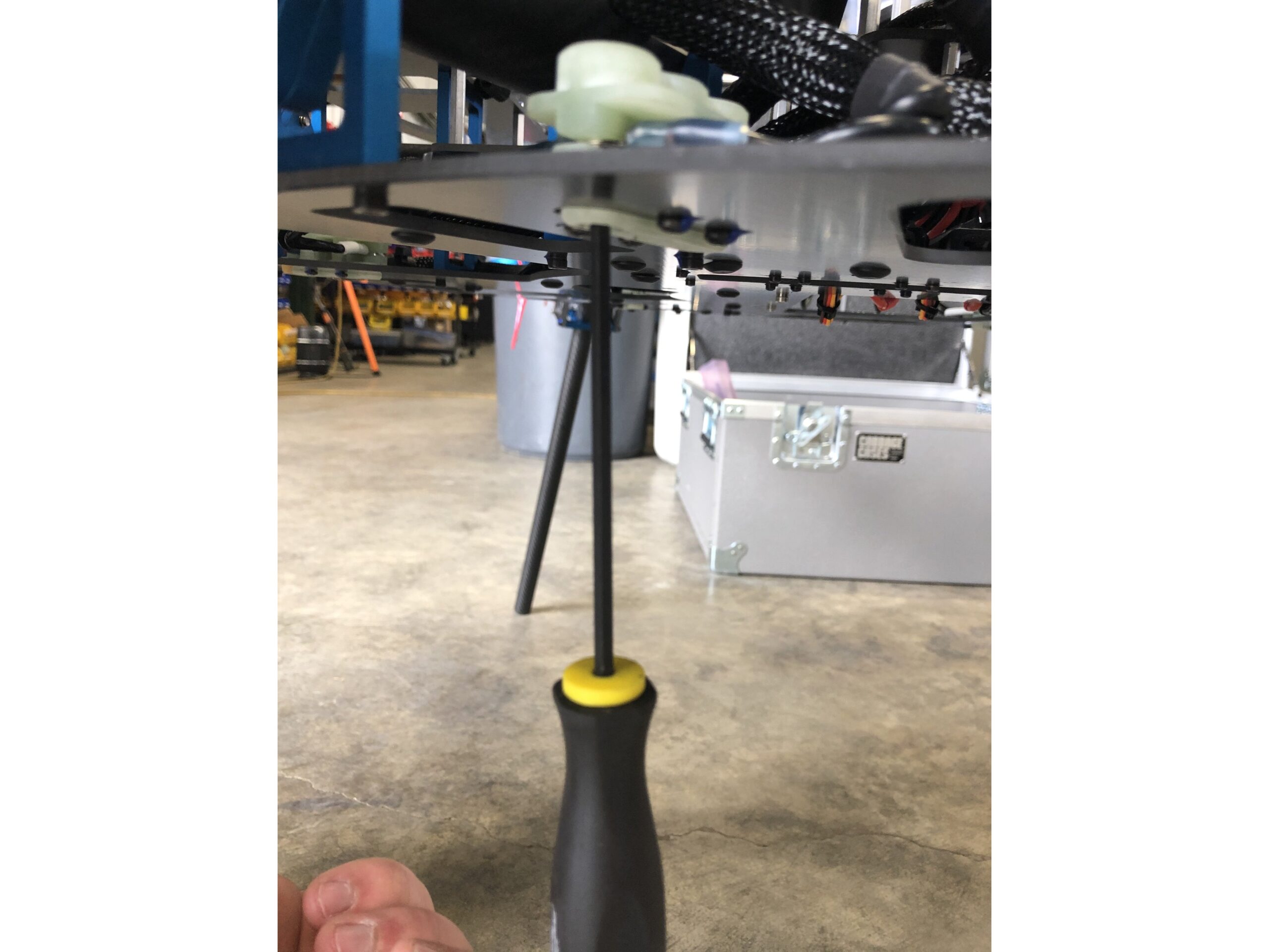
Use the provided 3/16 Hex Key to secure arm mount screws (3 per arm)
Use the provided 7/64 Hex Key to secure the landing gear tube to the landing gear mount
Click or Tap to expand images
Step 2
Securing Landing Gear
(Drones shipped after August 2025)
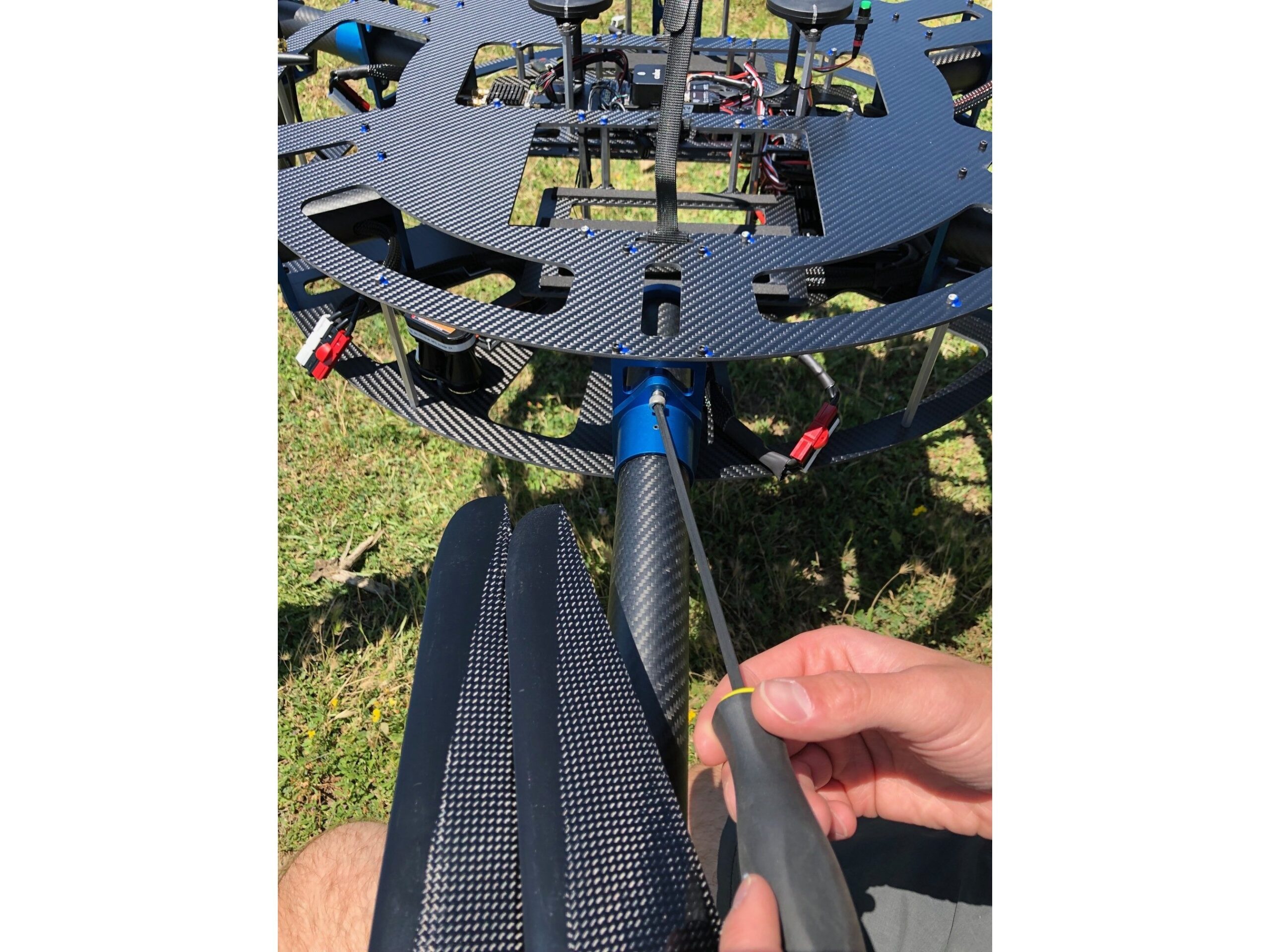
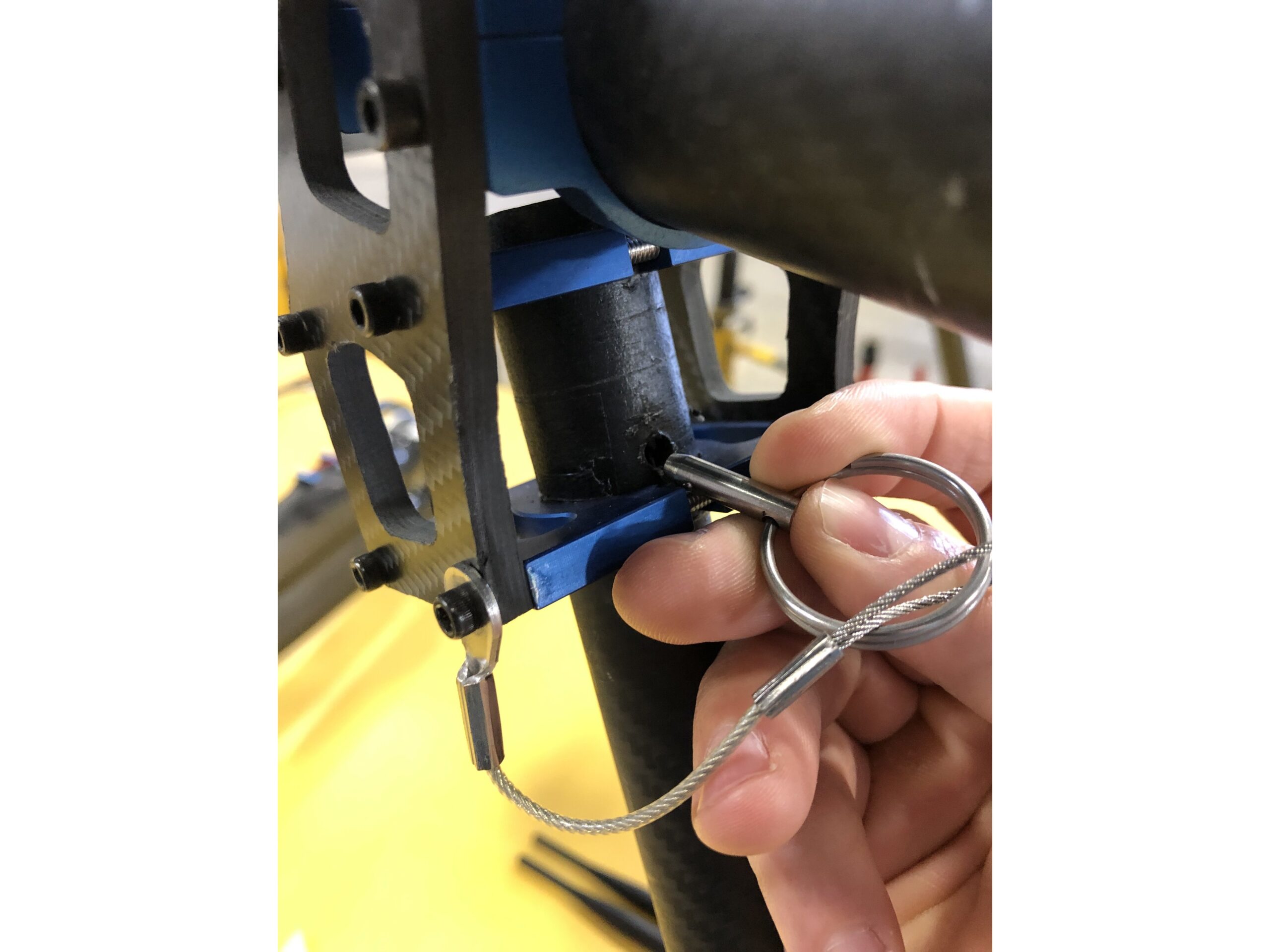
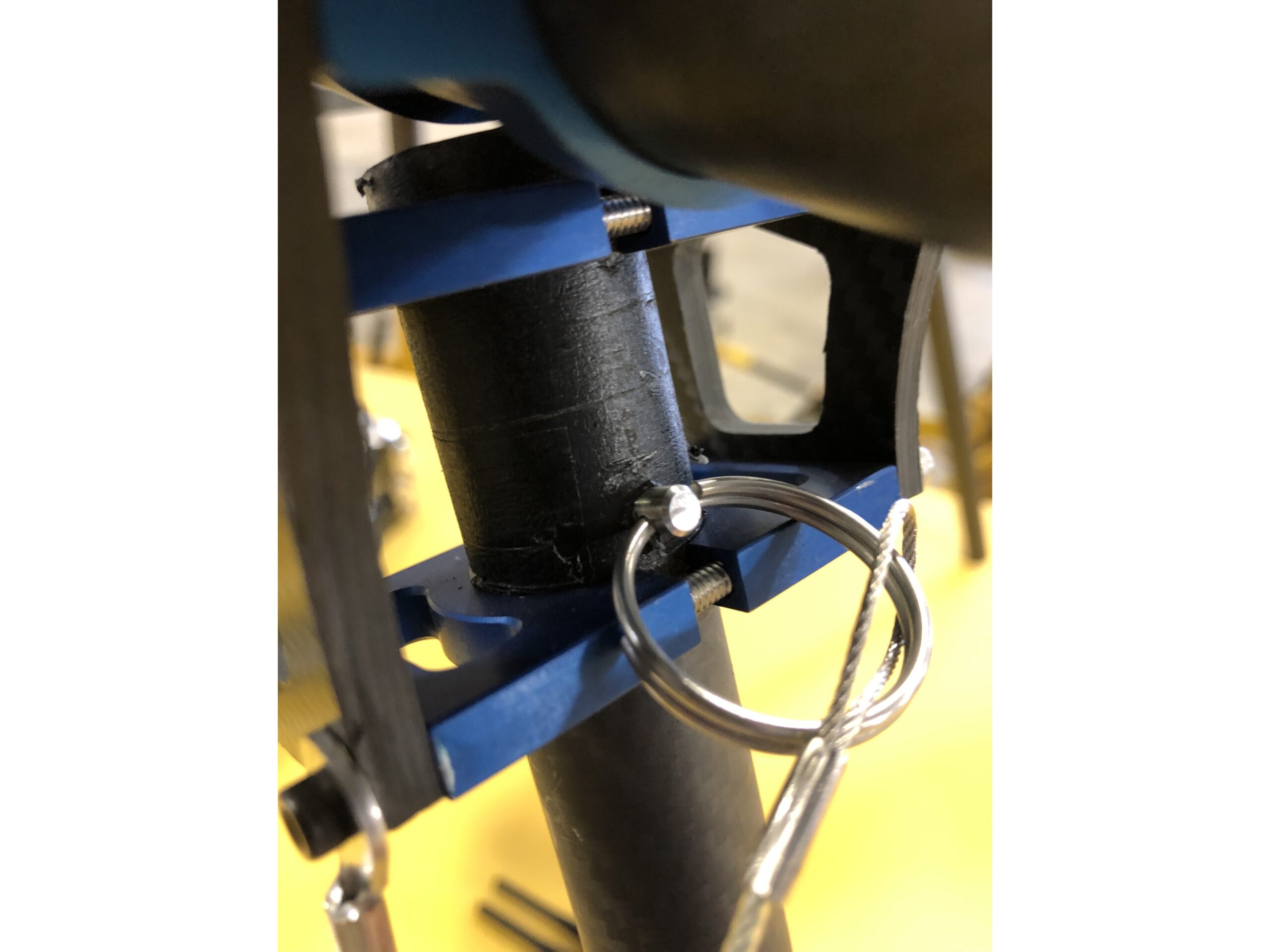
Fully seat the safety pin into the landing gear leg
Click or Tap to expand images
Step 2a
Securing Landing Gear (Legacy)
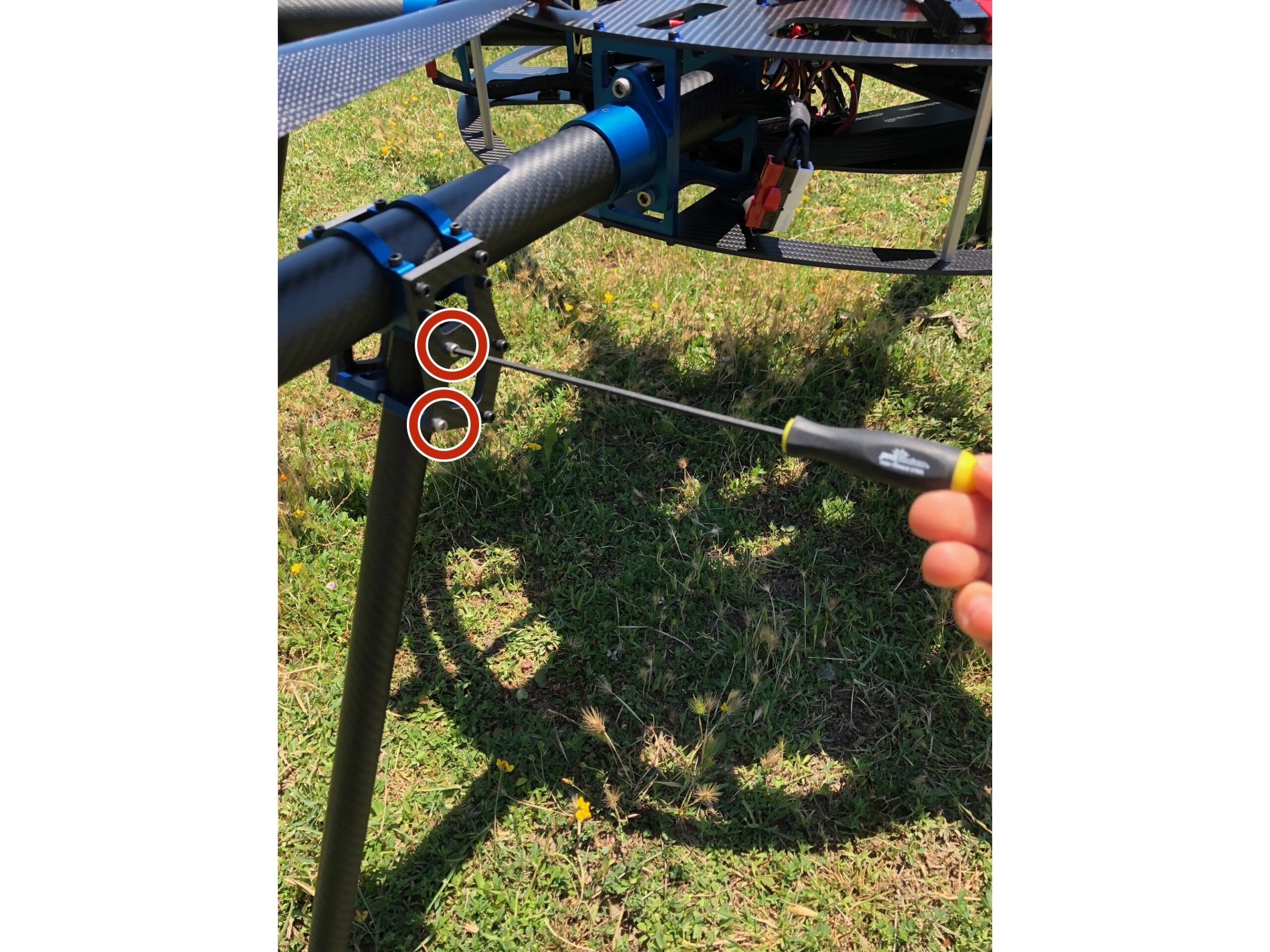
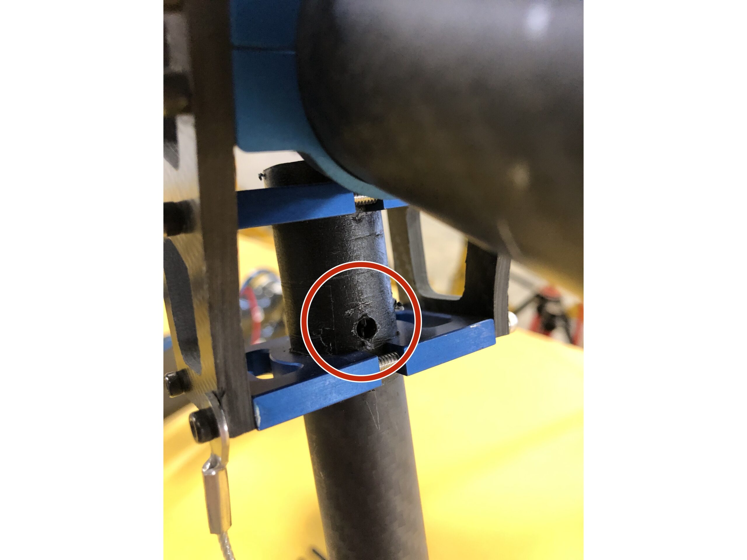
Using the mounted safety pin, fully insert into safety pin hole (above the lower bracket)
Note: the safety clip will connect between the red and black terminals
Click or Tap to expand images
Step 3
Connect Arm Terminals
(Drones shipped after August 2025)
Based on when your HLM was manufactured, you may have one of two types of arm terminals. For Drones shipped prior to August, 2025 please start at Step 3A or Step 3B depending on your configuration.
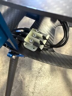
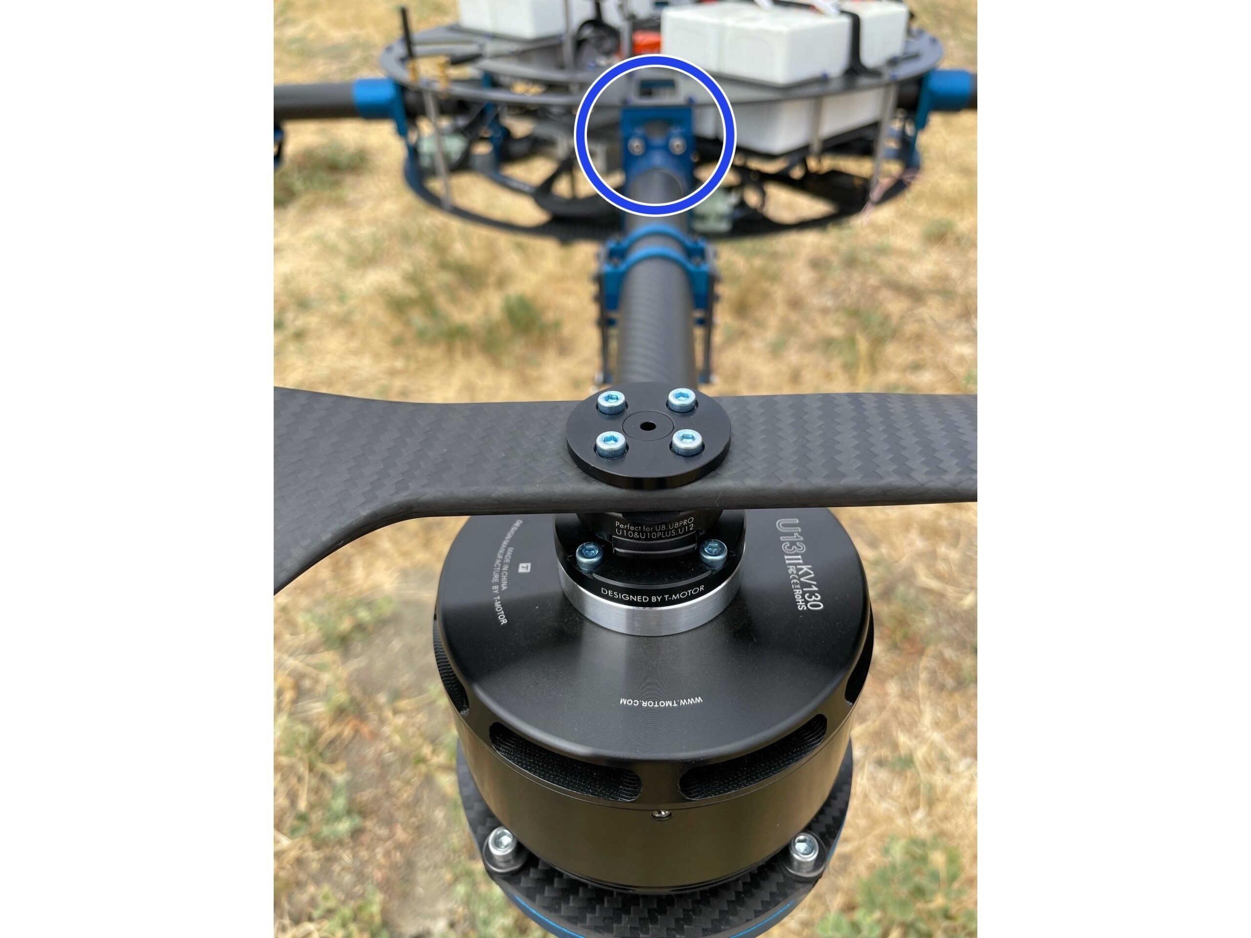
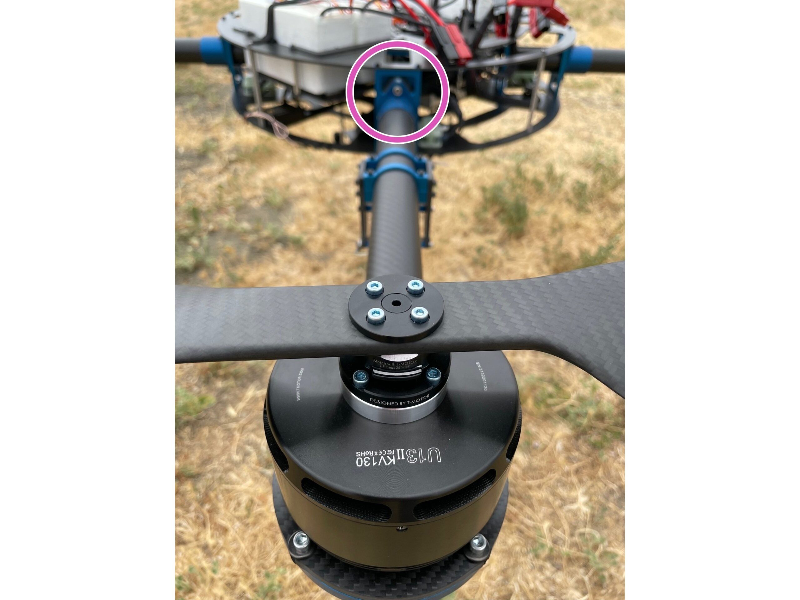
Using the included 9/64 ball driver, secure the motor arm 3-phase terminal block to the drone frame 3-phase terminal block.
This is a one-way attachment, please check alignment carefully!
Click or Tap to expand images
Step 3A
Arm Terminals (Legacy)
(Only for drones shipped prior to Dec 2020 that have been retrofitted)
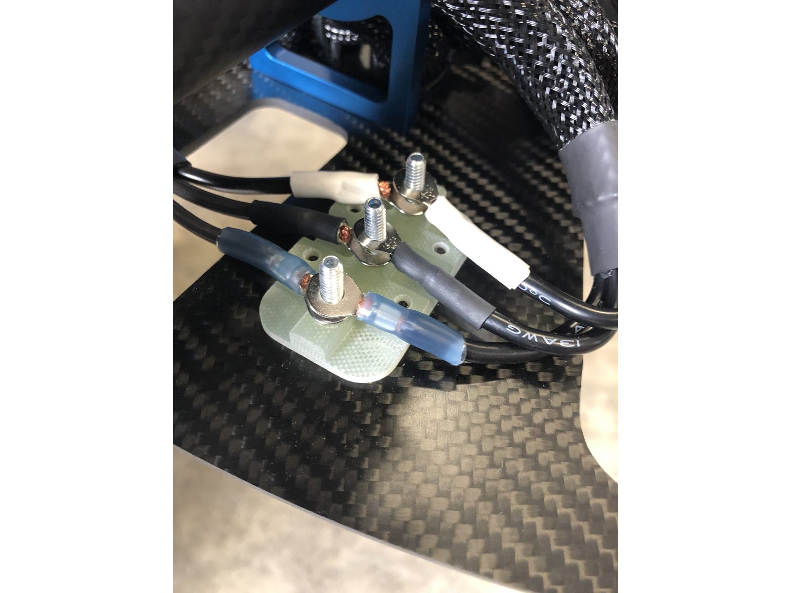
Connect corresponding arm terminals on post
Be sure to fasten corresponding colors to each other!
Use included 9/64 ball driver to securely fasten the upper terminal block
The lower terminal block is permanently fastened to the lower frame, do not remove!
Click or Tap to expand images
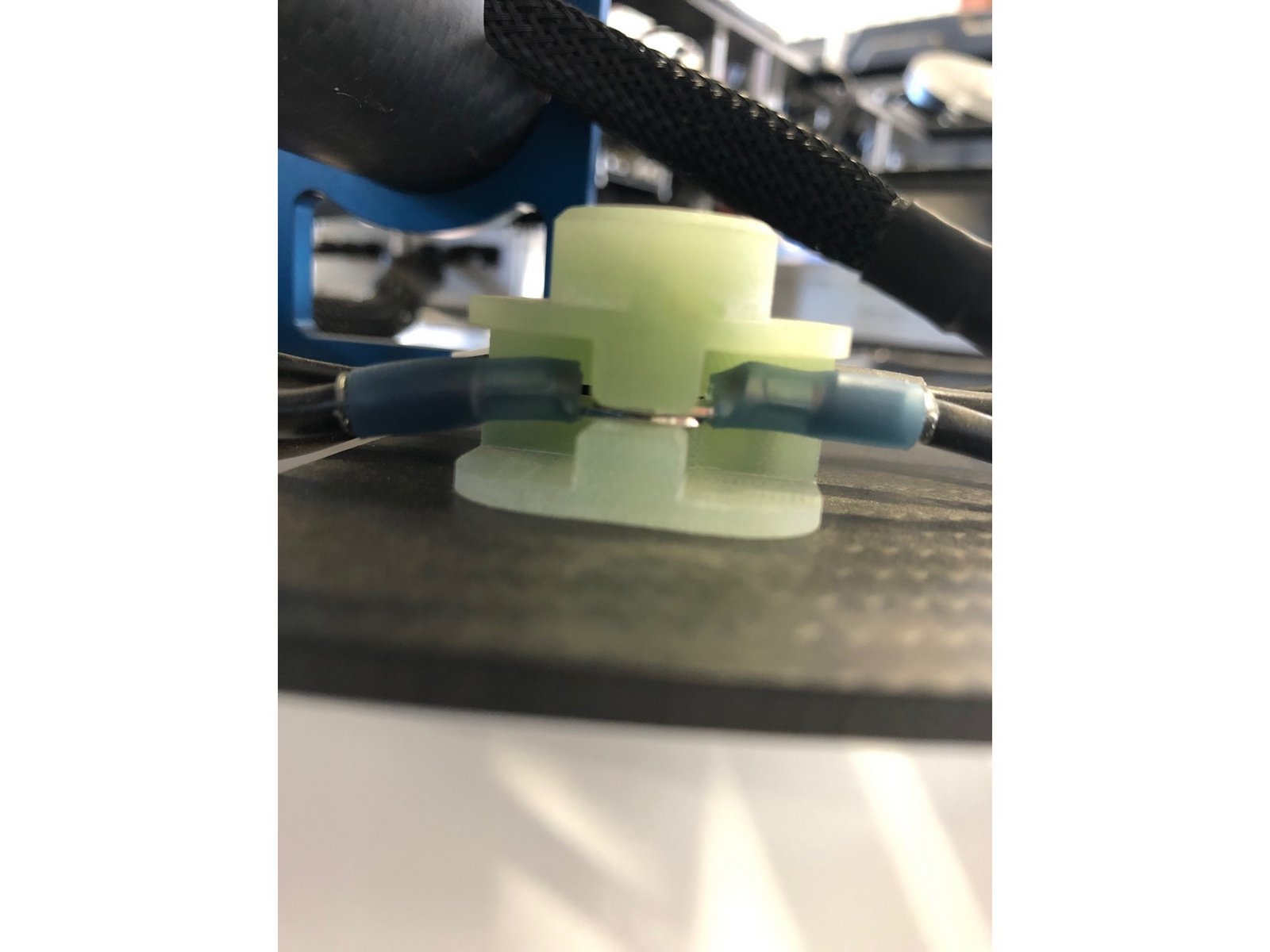
Step 3B
Terminal Block Fastening (Legacy)
(Drones shipped prior to August 2025)
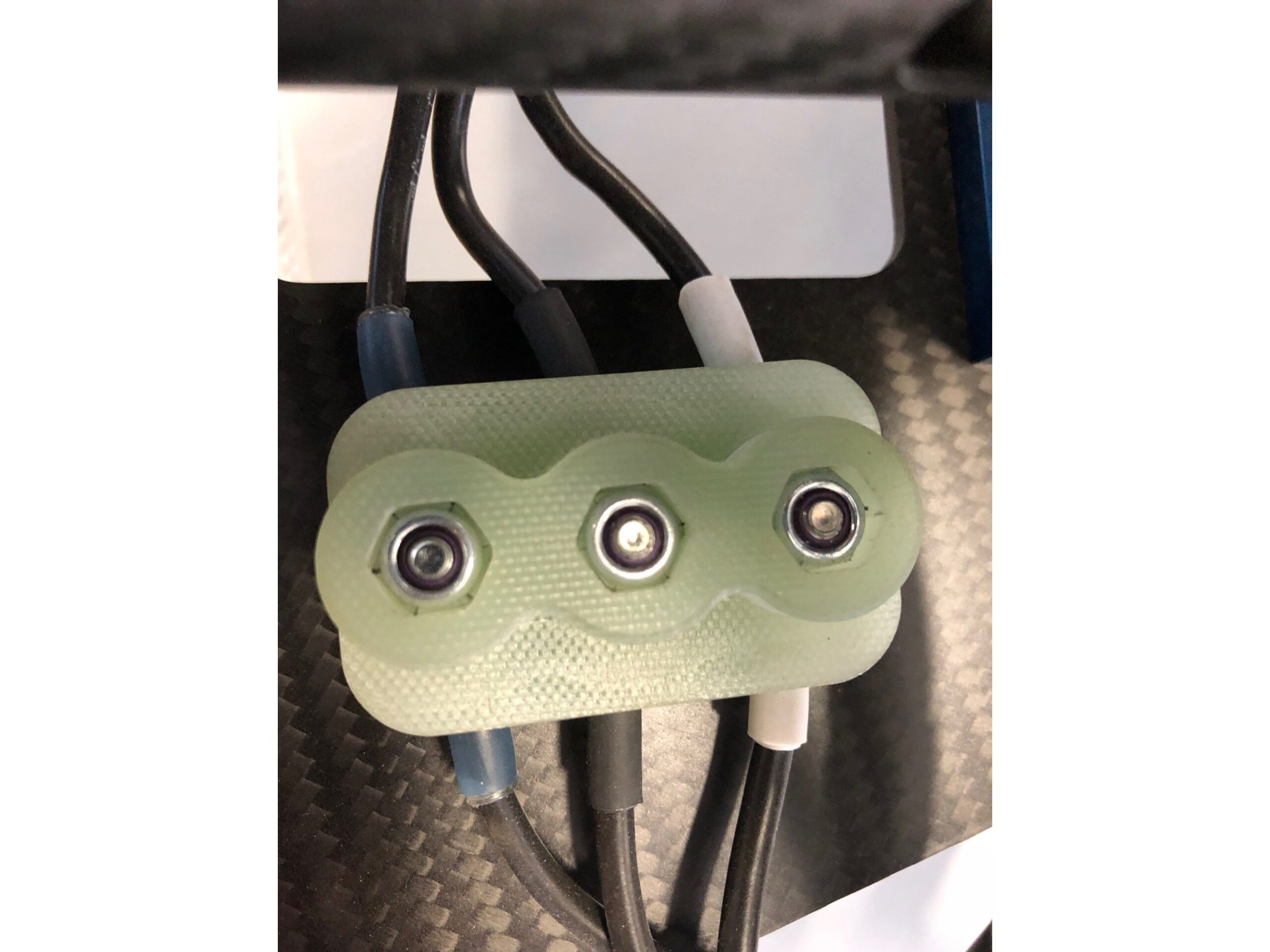
Ensure that the arm terminals are properly aligned (each terminal needs to stick straight out from the terminal block)
If the terminals are not properly straightened, the terminal block cannot be fully tightened. This can lead to power loss to the arm in flight
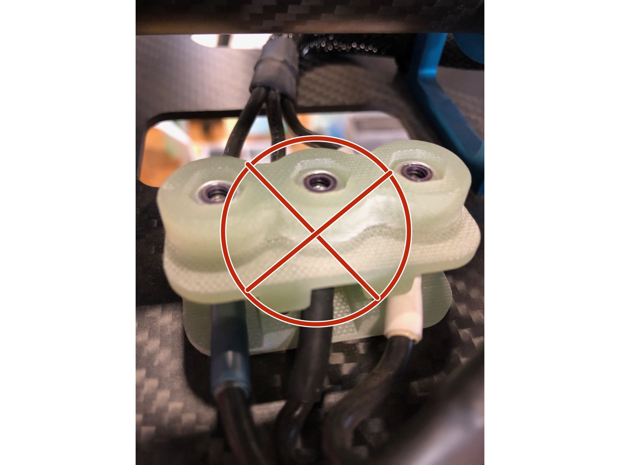
Make sure that the terminal lines do not impede the terminal block from fully seating (if they are crossed they will be pinched by the terminal block when tightening). This can lead to sparking and power loss to the arm in flight. (Picture 3)
Picture 3
Click or Tap to expand images
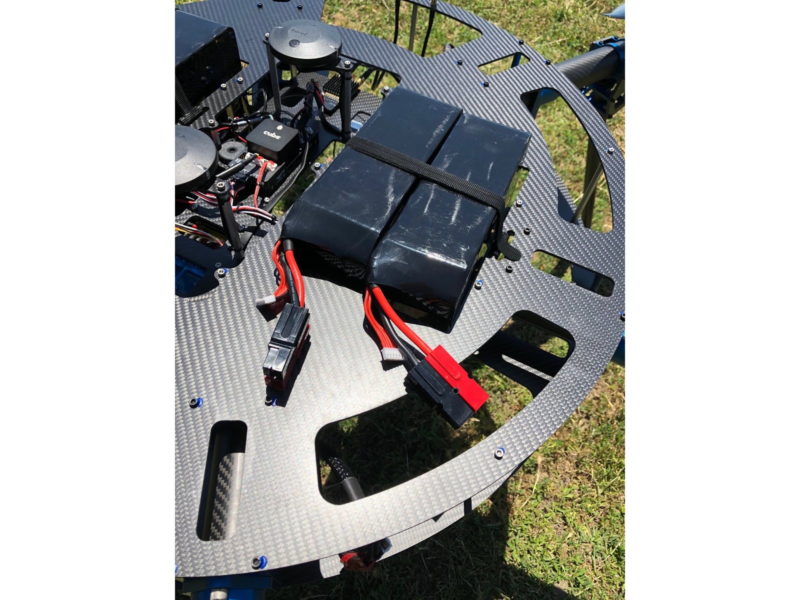
Step 4
Main Batteries
(Drones shipped after August 2025)
Secure the main batteries into the battery trays using the attached Velcro straps
Ensure that you have installed the correct battery chemistry (Li-Ion or Li-Po) based on what was ordered with your specific configuration
Do not power on the plane at this step!
Click or Tap to expand images
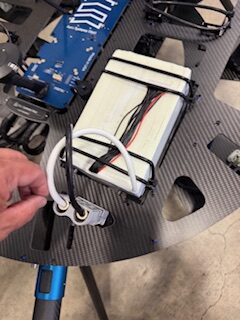
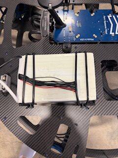
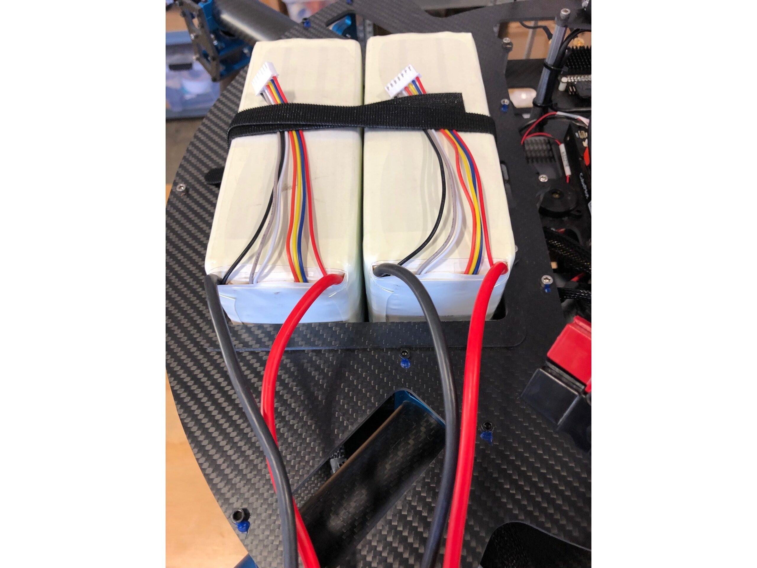
Step 4a
Main Batteries (Legacy)
(Drones shipped prior to August 2025)
Secure the main batteries into the battery trays using the attached Velcro straps
Ensure that you have installed the correct battery chemistry (Li-Ion or Li-Po) based on what was ordered with your specific configuration
Do not power on the plane at this step!
Click or Tap to expand images
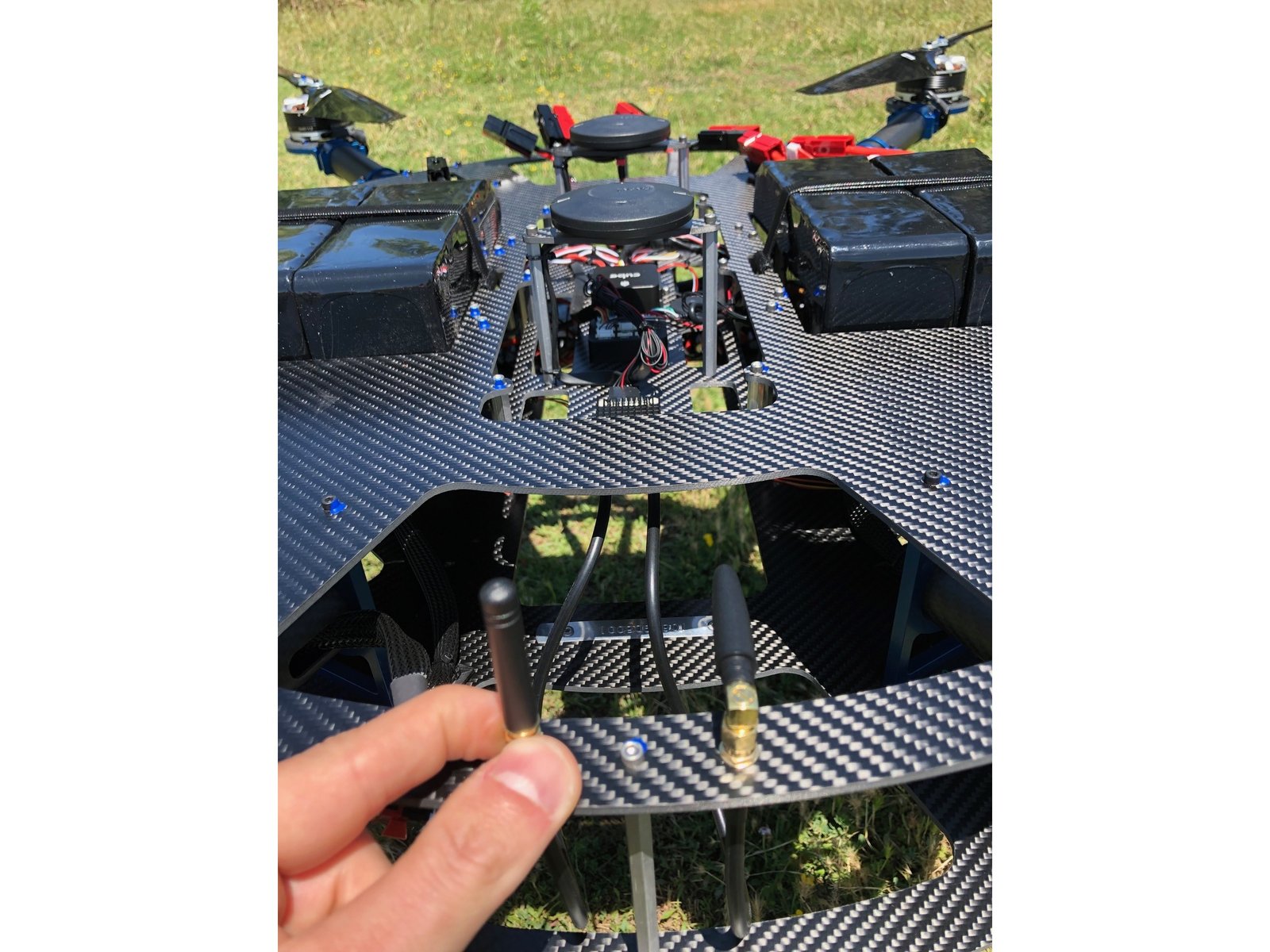
Step 5
Aircraft C2 Antenna
Check C2 antennas
Check that each antenna is securely fastened
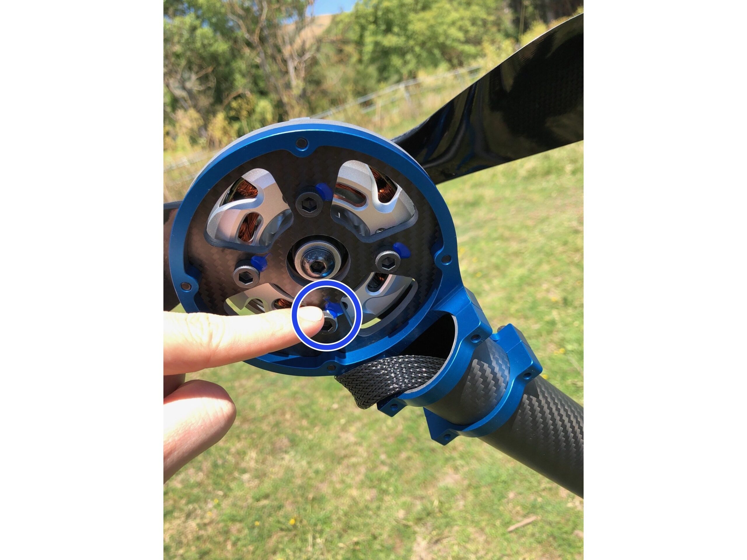
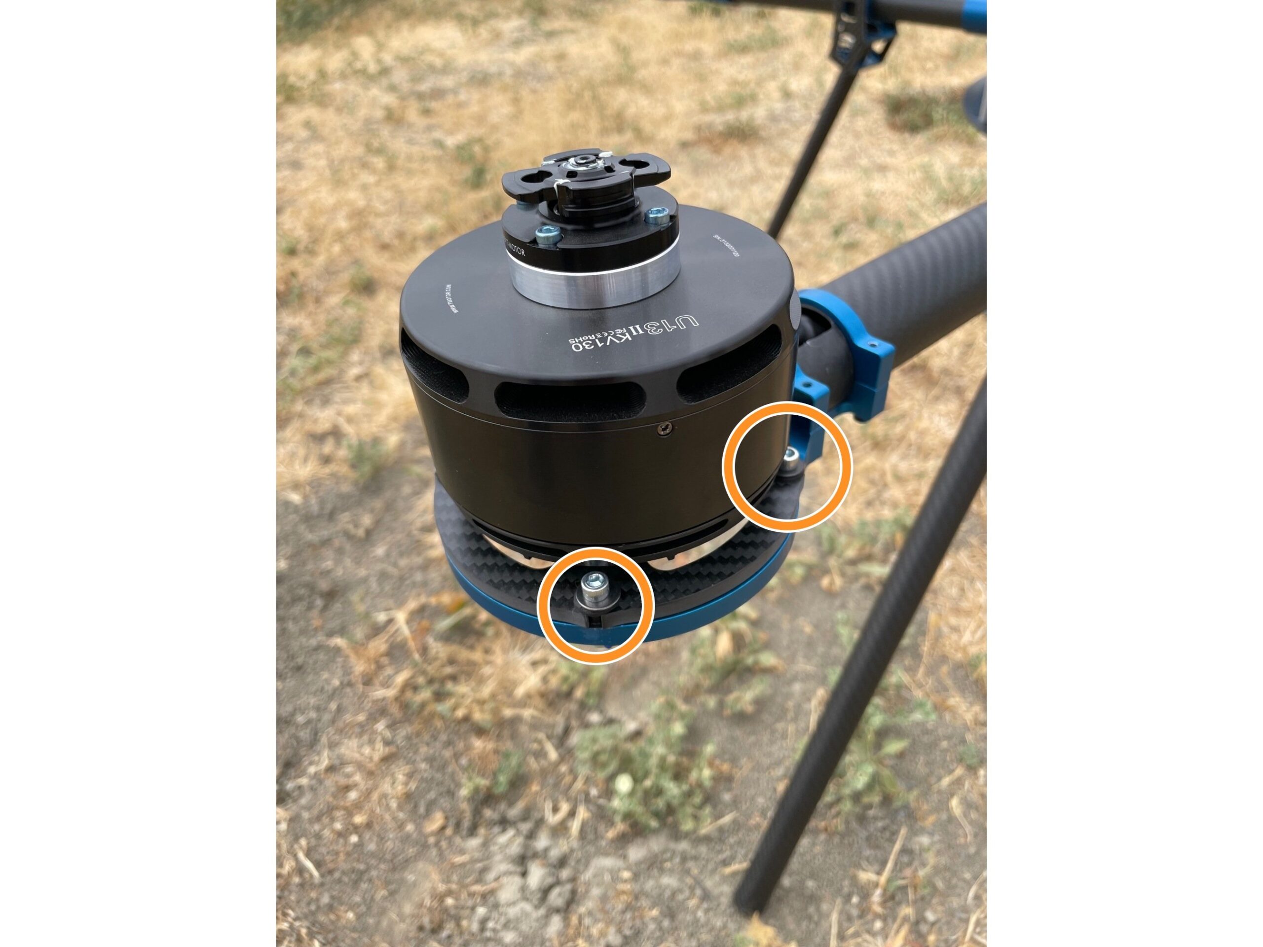
Step 6
Motors (regardless of type)
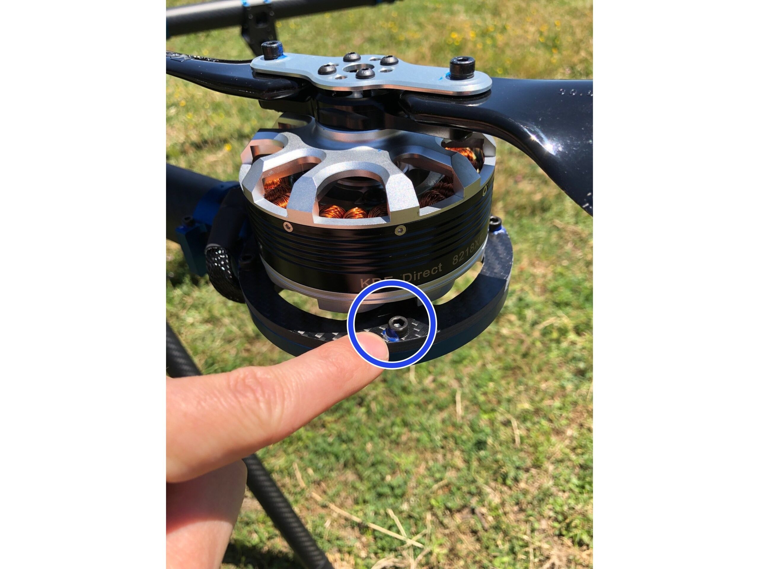
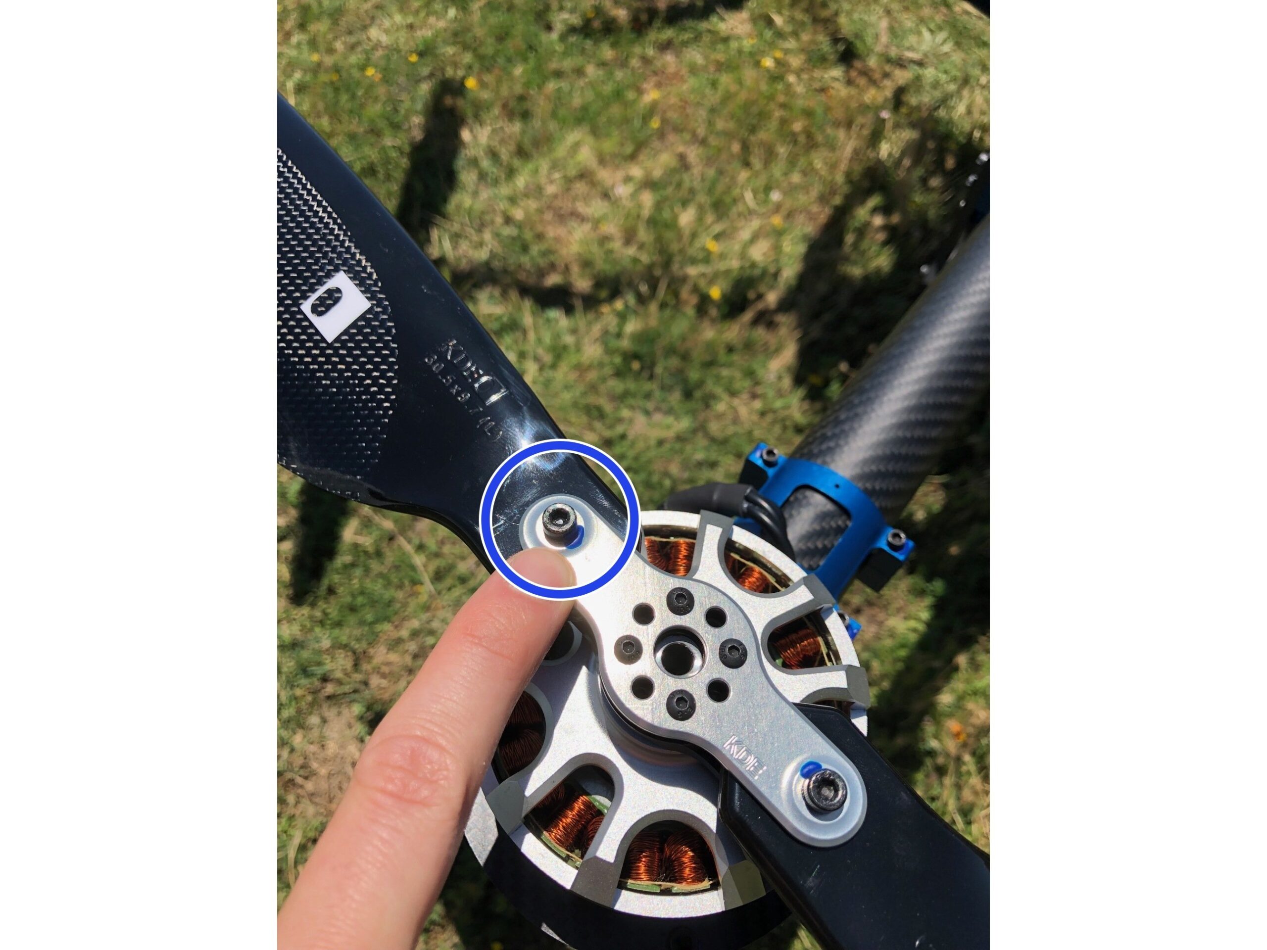
Ensure that the motors spin freely by hand
Check each lower motor mount screw for blue torque indicator (torque indicator should be intact with no cracking)
(Only for models configured with vibration mounts) Check each rubber dampener for excessive wear or chafing
Click or Tap to expand images
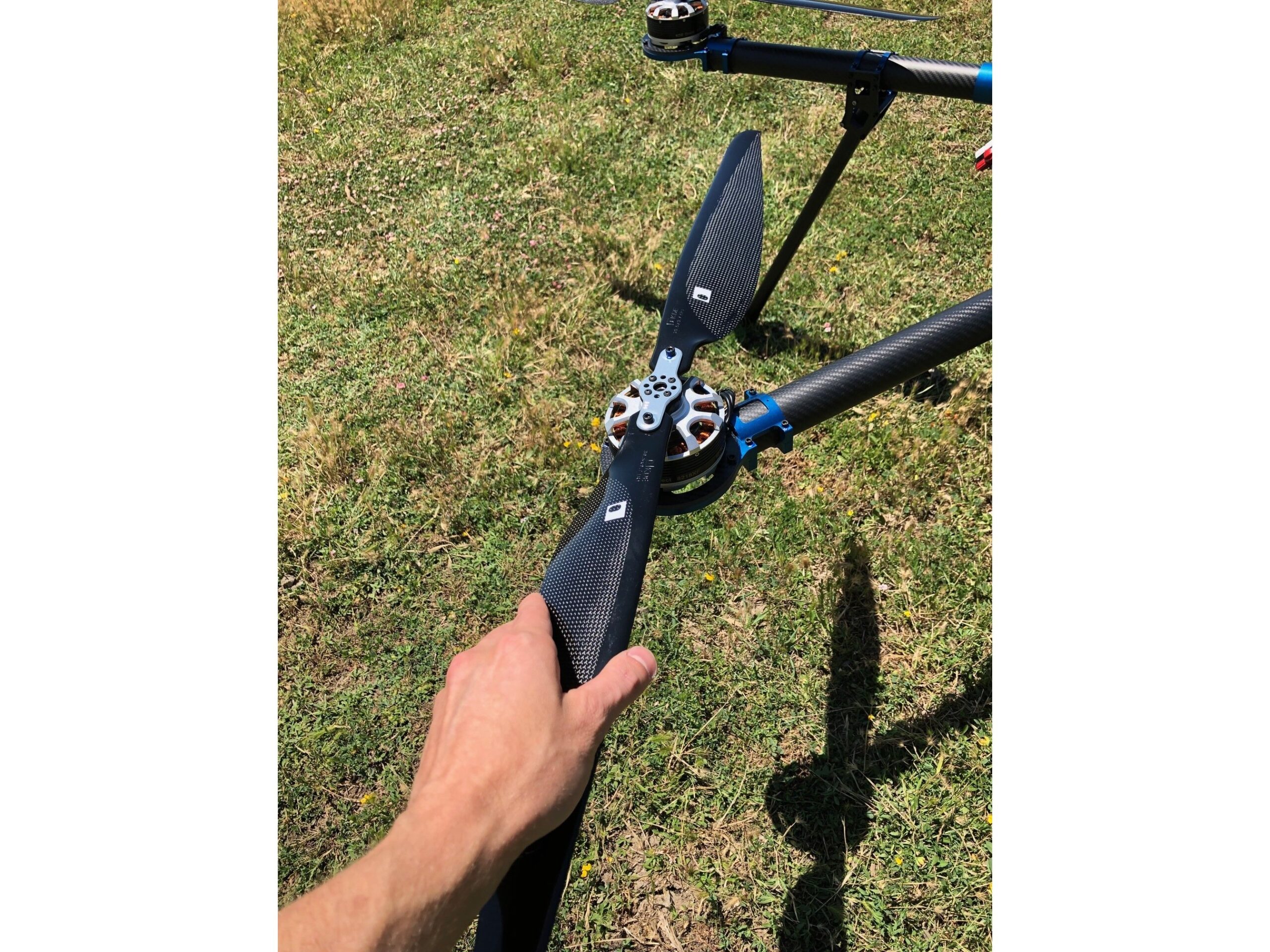
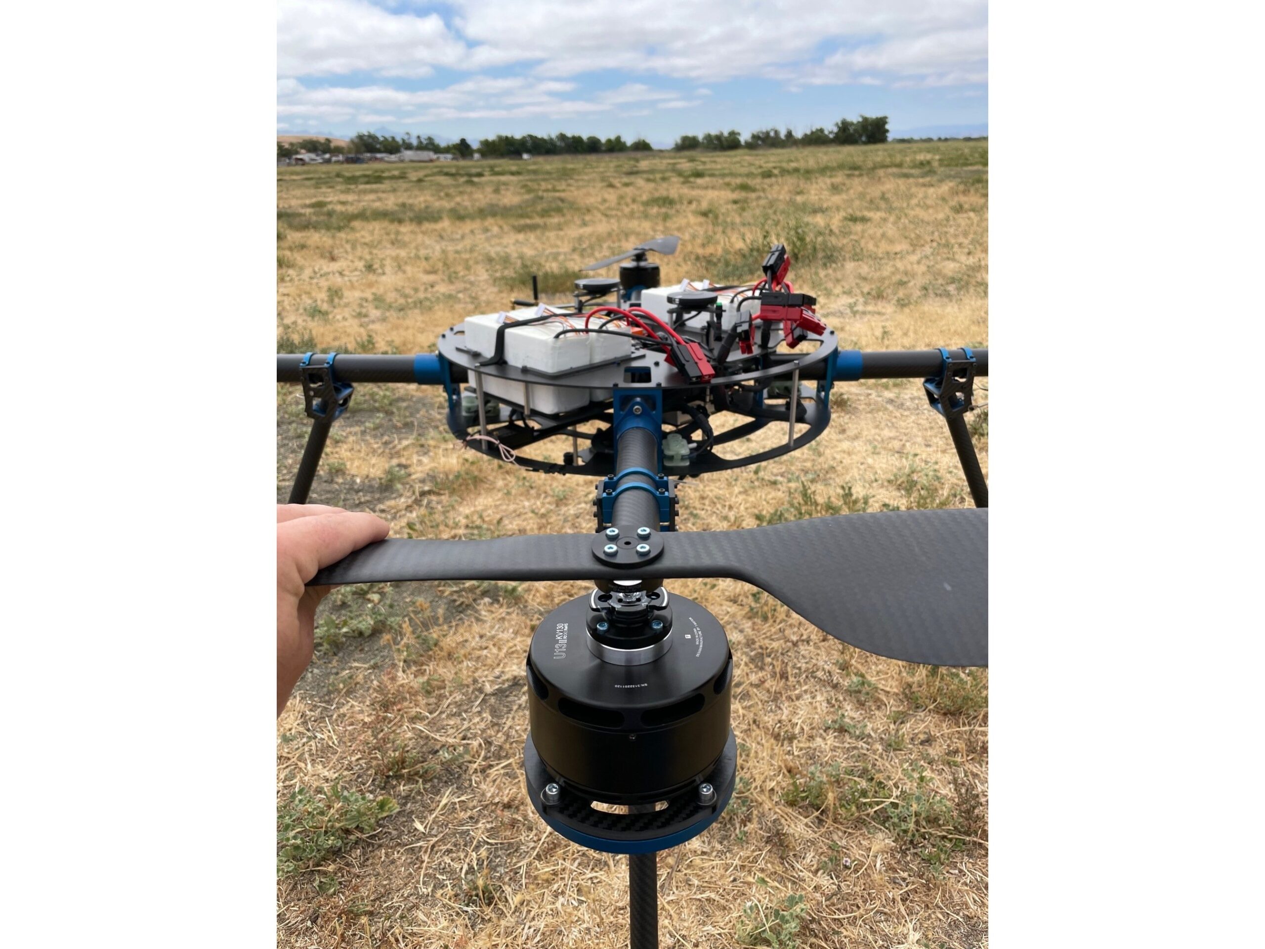
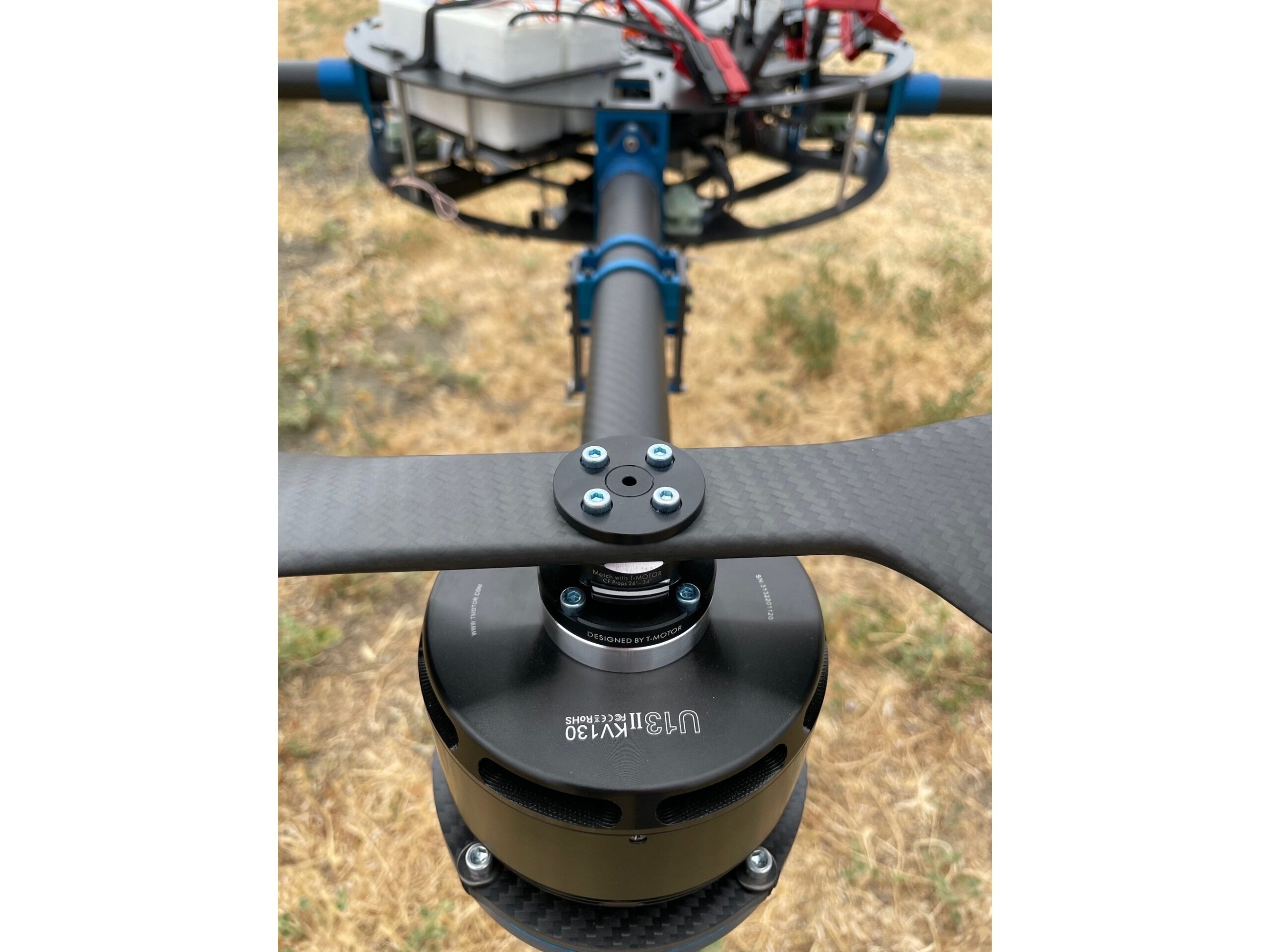
Step 7
Attach Propellers
(Only for models configured with T-Motor quick adapt propellers)
Line up corresponding marked propeller and quick adapters (clockwise propeller will be solid black, counter-clockwise propellers will have white markings)
Line up the propeller parallel with the quick adapter tabs and press down
Rotate the motor counter to the propeller direction, the quick adapter tabs will “click” upwards
Ensure that the propeller has seated fully in the quick adapter, the quick adapter tabs will be in an up position
Click or Tap to expand images
Step 8
Propeller Direction
Do not power on the plane at this step!
Clockwise propellers will have two tabs racing up at the arm root
Counter-clockwise arms will have one tabs facing up at the arm root
Click or Tap to expand images
Step 9
Frame
Check the integrity of torque indicator for any fastener on the drone on which indicator came installed
Click or Tap to expand images
Step 10
Payload
Customer specific
Ensure that your payload (if applicable) is safe for flight
From precision sensors to stealth startup prototypes, ASW’s heavy-lift platforms are engineered to integrate almost any payload—whether it’s off-the-shelf, in development, or one-of-a-kind. Common payloads can be mounted using our modular tray system. For specialized integrations, our engineering team can design a custom bolt-on interface tailored to your mission needs.
We don’t limit innovation—if it fits the platform and meets FAA guidelines, we’ll help you lift it.
Common Payload Types We Support:
Imaging & Visual Systems
RGB and DSLR cameras (Sony, Canon, Phase One)
EO/IR (Electro-Optical/Infrared) systems (CACI, Gremsy, Trillium etc.)
Thermal imaging cameras (FLIR, Workswell etc.)
Multispectral & hyperspectral sensors
360° panoramic and cinematic camera rigs
Your custom optical payloads, stealth systems, and more
Remote Sensing & Surveying
LiDAR systems (e.g., RIEGL, Velodyne, Livox)
Photogrammetry payloads
Ground Penetrating Radar (GPR)
Magnetometers and geophysical sensors
Atmospheric gas or air quality sensors
Prototype sensors and undisclosed research payloads welcome
Agricultural & Environmental
NDVI/multispectral crop health sensors
Spray systems for precision agriculture
Seed dispersal mechanisms
Environmental sampling probes
Wildlife observation & habitat mapping gear
Emerging environmental payloads and more
Delivery & Deployment
Package delivery containers
Medical supply drop kits
Controlled release mechanisms (servo-triggered)
Payload baskets and sling systems
Winch-and-drop delivery modules
Beta systems, test hardware, and field prototypes supported
Specialized & Tactical (Non-Weaponized)
Counter-UAS detection systems
RF jammers and signal intelligence sensors
Search & rescue (SAR) beacons and loudspeakers
High-powered spotlights or strobe arrays
Emergency communication repeaters
ISR Packages for public service agencies (drone as a first responder)
Custom Payload Support
Have something different in mind? We offer:
CAD-based payload fitment analysis
Custom trays, brackets, and dampening systems
Regulated/unregulated power interface design
Custom wiring, testing, and validation
Integration support for stealth programs and field tests
ASW offers training courses for all of the systems we sell. In-depth sessions are available for novice operators and those without existing certifications, while short courses are available for more experienced pilots simply requiring familiarity training on their new vehicle. Additionally, currency days with factory certified trainers are available for those who need to log flight time for operational requirements.
The team at ASW has extensive experience providing complex unmanned systems to civil and government customers. We can provide expert solutions to meet your requirements. Our services include:
In July of 2021, Aero Systems West, Inc. was acquired by Nippon Kayaku Company. This acquisition further advanced our commitment to enabling UAS flight safety. Nippon Kayaku Company has contributed to UAS safety through the development of high reliability fast deploying parachute safety devices. Through this acquisition, Nippon Kayaku Company and ASW have unified their visions and goals to deliver “Safety as a Standard.”
Aero Systems West is a California-based, US-made manufacturer and provider of heavy lift multirotor UAVs/UAS, backed by over a century of reliability and experience of our parent company, Nippon Kayaku.
Ready to explore our exceptional products and services? We’re thrilled to connect with you! Just fill out the quick form below, and our dedicated team will promptly reach out to assist you with any questions or inquiries you may have. Let’s embark on an exciting journey together!
Receive the latest news
Looking for fresh content?
We’ll deliver news about new products, sales and exclusive promos. Pretty cool right?